
Building product manufacturers can increase their chances of being specified by architects and designers by making high-quality design files available to the AEC community. Architecture firms use a range of different types of design content depending on the firm, and the types of construction projects they undertake. Among the product design content that manufacturers should supply to the design community is CAD drawings. CAD drawings are an integral part of construction contracts and they communicate information required for the successful completion of construction projects. 2D CAD is easily distributed and understood. Manufacturers should consider making CAD of their products available to architects and designers.
We spoke with Jill Clark, Senior CAD Manager at CADdetails, about how to read a CAD drawing, and what building product manufacturers and landscape product manufacturers should keep in mind when considering CAD development for their products.
Where Should I Start Reading a CAD Drawing?
Start with the title or title block. This indicates drawing details such as project names, created or revision date of the CAD drawing, the number of pages, various notes relating to construction on installation, and possibly information about the scale of the drawing. CADdetails drawings created for manufacturers, the title block has our standard notes, manufacturer’s information, CADdetails copyright, and our revision/creation date.
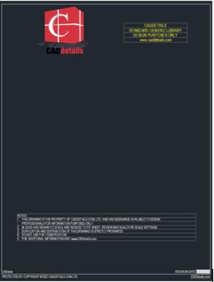
This is our generic title block that would be uploaded and customized to each manufacturer.
The second item or detail to look at while reading a CAD drawing is the drawing block or graphical portion of the CAD drawing. This may give you information about the nature of the product, the size of the product and where it should be installed. In the case of CAD drawings by CADdetails, this is where the manufacturer's information and details would be depicted on our A-Size sheet. There are also other information blocks to pay attention to. These provide details about what the drawing is for and who the drawing is for. Information such as part numbers and descriptions may also be included.
Determine the View
There are different views in a CAD drawing. The appropriate view will depend on what is being shown. There are several different types of plan views that are found in CAD drawings. Floor plan views depict the interior as if the ceiling was removed. Site plans are similar to floor plans but show an entire building. Reflective ceiling plans are similar to floor plans, except showing a reflection of a ceiling. Millwork drawings indicate all details and are often used for showing all pieces involved in the construction of a product. Section views cut through an object and show how products are installed or what is happening behind a wall or surface. Elevation views are from the side of an object. For interior elevations, this could be a wall including windows or anything in direct contact with the wall. Exterior elevations show the outside of a building and are useful to show what a building should look like when construction is complete. Landscape plans show exterior features such as gardens, paths, plans, and decorations.
Two views that are less useful for designers are isometric and perspective views. Both of these are more of a marketing tool and do little to help designers looking to include a manufacturer’s product in their plans. Isometric views are 3D and ignore dimensions and visually represent a three-dimensional object in two dimensions in technical and engineering drawings. Perspective views are graphic art drawing representations on a flat surface from a point of view that one would see when viewing the object or space.
What Else is Found in CAD Drawings?
CAD drawings include dimensions, notations, and symbols required for understanding the drawing. Every drawing will have dimension lines and they communicate essential information such as electrical, structural, or plumbing placement.
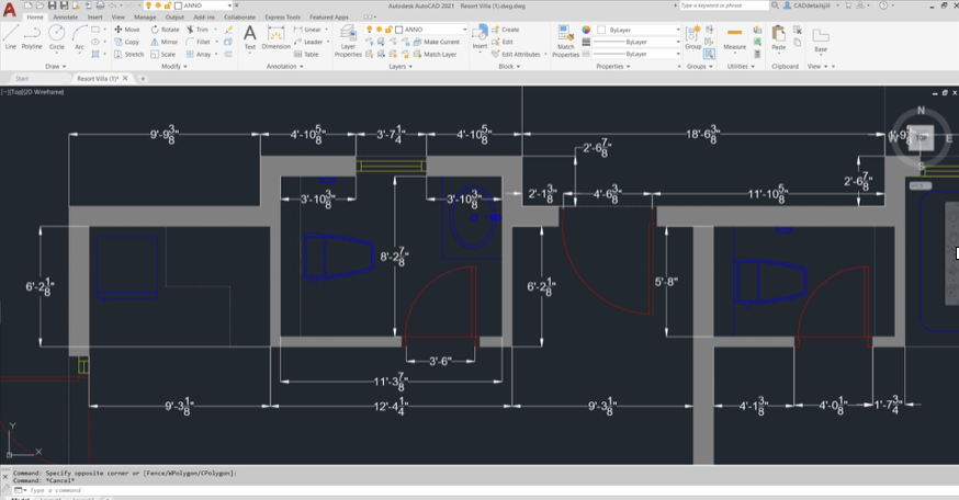
A CAD drawing with dimension lines shown in white.
Why are there Different Colors in a CAD drawing?
CAD drawings have a layering system that separates each component from each other, usually separated by different line colors and line types. This allows the architect or designer to find exact products, lighting, windows and doors easily on any plan.
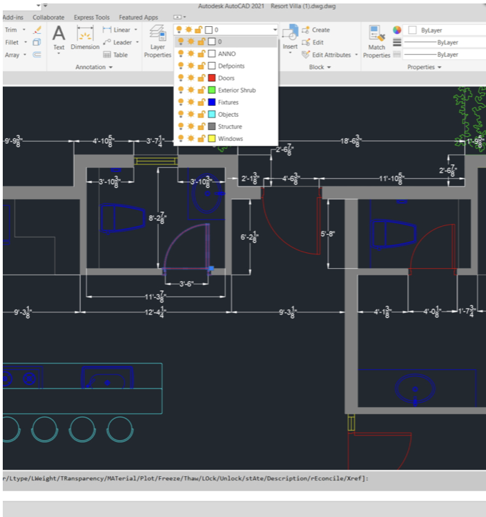
An example of a layering system. In this case, the doors are red.
What Are the Different Types of Lines?
Drawings include visible lines and hidden lines. Visible lines are just that, they indicate an edge that is visible. Hidden line types indicate an edge not visible from the relevant view. This is often used for objects that are beneath other objects. There are also phantom lines that indicate an alternate position of a moving part. Sometimes centerlines are found in a CAD drawing to indicate the geometric center of an assembly.
How Do CADdetails Drawings Stand Apart from Other CAD Drawings?
Drawings created by CADdetails are product drawings for manufacturers to provide to the AEC community. The same standards and layering systems across all of our drawings. This helps designers easily use different products from a range of manufacturers in their projects. CADdetails drawings are created in an A size (printer page size) format for ease of use.
What Makes CADdetails Drawings Ideal for Manufacturers?
By having the same standards and layering systems across all of our drawings, we help designers use different manufacturers in their projects. Designers using our site know they can find new products on our site and easily incorporate their CAD drawings into their plans. CADdetails provide useful information to designers and provide participating manufacturers with a competitive advantage when it comes to having their products included in construction project plans.
What are CADdetails Drawings Used For?
CADdetails drawings are used by designers in the planning stages of their projects. Our drawings are also used in the bidding process and can be incorporated into plans, elevations, sections, and architectural drawings of any kind.
How Do CADdetails Drawings for Manufacturers Differ from CAD Drawings Created for a Construction Project?
The drawings we develop for manufacturers show the products you would use in a project. Project drawings can show many different areas of design that could include multiple products shown on CADdetails. Designers can obtain blocks and details from our drawings and manipulate it to suit their project's needs.
What Information Should Manufacturers Provide CADdetails to Create the Best Possible Drawings for Their Products?
Information about various options is important to include such as available sizes and colors for a product. Additional information about your specific product may also be included. Any kind of file type that they may have for their product, 3D or 2D is extremely useful for our CAD Technicians at CADdetails
If you are a building product manufacturer or landscape product manufacturer interested in reaching architects and designers by having high-quality CAD available for your products, please reach out to us to talk about CADdetails participation and CAD development.